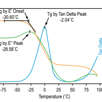
Dynamic mechanical analysis (DMA), also known as forced oscillatory measurements and dynamic rheology, is a basic tool used to measure the viscoelastic properties of materials (particularly polymers). To do so, DMA instrument applies an oscillating force to a material and measures its response; from such experiments, the viscosity (the tendency to flow) and stiffness of the sample can be calculated.
Interaction of an electron beam with a sample target produces a variety of emissions, including x-rays. An energy-dispersive (EDS) detector is used to separate the characteristic x-rays of different elements into an energy spectrum, and EDS system software is used to analyze the energy spectrum in order to determine the abundance of specific elements. EDS can be used to find the chemical composition of materials down to a spot size of a few microns, and to create element composition maps over a much broader raster area. Together, these capabilities provide fundamental compositional information for a wide variety of materials.
EDS systems are typically integrated into either an SEM or EPMA instrument. EDS systems include a sensitive x-ray detector, a liquid nitrogen dewar for cooling, and software to collect and analyze energy spectra. The detector is mounted in the sample chamber of the main instrument at the end of a long arm, which is itself cooled by liquid nitrogen. The most common detectors are made of Si(Li) crystals that operate at low voltages to improve sensitivity, but recent advances in detector technology make availabale so-called “silicon drift detectors” that operate at higher count rates without liquid nitrogen cooling.
An EDS detector contains a crystal that absorbs the energy of incoming x-rays by ionization, yielding free electrons in the crystal that become conductive and produce an electrical charge bias. The x-ray absorption thus converts the energy of individual x-rays into electrical voltages of proportional size; the electrical pulses correspond to the characteristic x-rays of the element.
Strengths
When used in “spot” mode, a user can acquire a full elemental spectrum in only a few seconds. Supporting software makes it possible to readily identify peaks, which makes EDS a great survey tool to quickly identify unknown phases prior to quantitative analysis.
EDS can be used in semi-quantitative mode to determine chemical composition by peak-height ratio relative to a standard.
Limitations
There are energy peak overlaps among different elements, particularly those corresponding to x-rays generated by emission from different energy-level shells (K, L and M) in different elements. For example, there are close overlaps of Mn-Kα and Cr-Kβ, or Ti-Kα and various L lines in Ba. Particularly at higher energies, individual peaks may correspond to several different elements; in this case, the user can apply deconvolution methods to try peak separation, or simply consider which elements make “most sense” given the known context of the sample.
Because the wavelength-dispersive (WDS) method is more precise and capable of detecting lower elemental abundances, EDS is less commonly used for actual chemical analysis although improvements in detector resolution make EDS a reliable and precise alternative.
EDS cannot detect the lightest elements, typically below the atomic number of Na for detectors equipped with a Be window. Polymer-based thin windows allow for detection of light elements, depending on the instrument and operating conditions.
Results
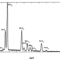
A typical EDS spectrum is portrayed as a plot of x-ray counts vs. energy (in keV). Energy peaks correspond to the various elements in the sample. Generally they are narrow and readily resolved, but many elements yield multiple peaks. For example, iron commonly shows strong Kα and Kβpeaks. Elements in low abundance will generate x-ray peaks that may not be resolvable from the background radiation.
EDS spectrum of multi-element glass (NIST K309) containing O, Al, Si, Ca, Ba and Fe (Goldstein et al., 2003). Details
EDS spectrum of biotite, containing detectable Mg, Al, Si, K, Ti and Fe (from Goodge, 2003). Details
References
Severin, Kenneth P., 2004, Energy Dispersive Spectrometry of Common Rock Forming Minerals. Kluwer Academic Publishers, 225 p.–Highly recommended reference book of representative EDS spectra of the rock-forming minerals, as well as practical tips for spectral acquisition and interpretation.
Goldstein, J. (2003) Scanning electron microscopy and x-ray microanalysis. Kluwer Adacemic/Plenum Pulbishers, 689 p.
Reimer, L. (1998) Scanning electron microscopy : physics of image formation and microanalysis. Springer, 527 p.
Egerton, R. F. (2005) Physical principles of electron microscopy : an introduction to TEM, SEM, and AEM. Springer, 202.
Clarke, A. R. (2002) Microscopy techniques for materials science. CRC Press (electronic resource)
[corner-ad id="1"]
Analysis and interpretation of thermogravimetric analysis (TGA) results
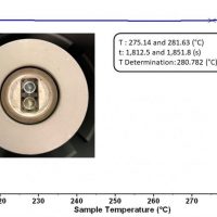
TGA is a powerful and robust technique to explore the thermal stability of a material. By accurately monitoring the weight of a sample while heating at a constant rate, we can measure changes in a sample’s weight and attribute this to a specific material response to a thermal stress (Figure 1). This is perfect for exploring, in detail, decomposition temperatures and ensuring a material performs adequately in a given temperature range.
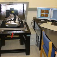
Atomic force microscopy (AFM) or scanning force microscopy (SFM) is a very-high-resolution type of scanning probe microscopy (SPM), with demonstrated resolution on the order of fractions of a nanometer, more than 1000 times better than the optical diffraction-limit.
To satisfy this curiosity, many inventions have been devised. One of them is the optical microscope. The human eye can distinguish objects down to about 0.2 mm. Optical microscopes reveal small objects, which would be otherwise invisible to the human eye, by magnifying them with the help of a combination of glass lenses. If we raise the amplification rate (magnification) of an optical microscope higher and higher, can we see an atom?
The scanning electron microscope (SEM) uses a focused beam of high-energy electrons to generate a variety of signals at the surface of solid specimens. The signals that derive from electron-sample interactions reveal information about the sample including external morphology (texture), chemical composition, and crystalline structure and orientation of materials making up the sample.
Raman spectroscopy is a powerful vibrational technique used widely in chemistry, materials science, geology, biology, and industrial laboratories. To make the most of this analytical tool, proper software is essential for spectrum acquisition, visualization, processing, and interpretation. While many commercial solutions exist, there are also free and open tools that are capable, flexible, and ideal for researchers, students, and laboratories on a budget.
It is the shift in wavelength of the inelastically scattered radiation that provides the chemical and structural information. Raman shifted photons can be of either higher or lower energy, depending upon the vibrational state of the molecule under study. A simplified energy diagram that illustrates these concepts is shown below.
Light interacts with matter in different ways, transmitting through some materials, while reflecting or scattering off others. Both the material and the colour (wavelength) of the light affect this interaction. We call the study of this light ‘spectroscopy’. Which parts of the visible spectrum enter our eyes determines which colours we perceive.
Driven by applications in chemical sensing, biological imaging and material characterisation, Raman spectroscopies are attracting growing interest from a variety of scientific disciplines. The Raman effect originates from the inelastic scattering of light, and it can directly probe vibration/rotational-vibration states in molecules and materials.